Accident 3
Deterioration of equipment
Sequence of events
An explosion occurred in a granulation dryer at a factory manufacturing initiative explosives for electric detonators. Diazodinitrophenol, which is an initiating explosive of an electric detonator, explodedin a drying and granulating process. The explosion damaged produc-tion lines and shattered glass in the factory building. Nobody was hurt in the accident, due to the fact that the facility where the explosion occurred was usually automated and nobody worked there. Employees produced the explosives by remote control from outside.
Causes
Although the causes could not be entirely confirmed, the company focused speculation on two possibilities:
1) The diazodinitrophenol accidentally entered into a crack in a splitter plate that was fixed to the dryer of a granulating machine with an adhesive agent. As a result, diazodinitrophenol ignited due to friction, then burned and detonated.
2) Iron rust contaminated the diazodinitrophenol in the granulating machine causing its friction sensitivity to increase. Therefore, diazodinitrophenol ignited in the granulating process, burned, and detonated.
Important findings
• This was the first accident experienced at the plant. It seems that the company took insufficient care for age degradation.
• Safety management did not take sufficient account of sensitive materials, such as initiating explosives.
Lessons learned
• Even though corrosion is a well-known phenomenon in oil refineries, it is not necessarily a hazard considered in explosive factories. This scenario, however, should be discussed in relevant hazard identification studies on such sites. This accident demonstrates that the risk potential of corrosion in explosion manufacturing is not only enhanced by equipment degradation but also by the presence of dust particles created by the corrosion process.
• Explosives manufacturing are particularly high risk with enormous potential to generate catastrophic accidents. Failure to conduct thorough hazard identification and risk analyses is not an option. With explosives, there is absolutely no time for intervention if something goes wrong, so it has to be of paramount importance to the operator that nothing goes wrong. Although this particular accident involved an automated process, and no employees were present, the material damages incurred significant costs. Even automated process should be routinely inspected and audited at these sites to avoid significant business losses and possibly other unintended consequences.
[ http://www.sozogaku.com/fkd/en/cfen/CC1300005.html]
|
Accident 4
Wrong equipmen
Sequence of events
On 5th January 2008 a production operator discovered a fairsized phenol leak in the phenol pump house next to the phenol storage tank. One of the gaskets on the flange connection on the outlet pipe of the tank had failed. The head of the operations department tried to stop the leak by tying a rubber belt around the flange. In the meantime, an operator sprayed water on the flange to avoid contact with phenol as much as possible. The phenol that had leaked was collected in a catchment pit of 20 m3 underneath the pump house. This catchment pit had a high level alarm, but it was not functioning at the time of the leak. The company was not aware of the malfunction because the alarm was not subject to periodic inspection.
An attempt was made to close the only manual valve on the pipe, located between the inner and the outer tank shells, but the valve spindle broke off during this manipulation, so the line could not be shut off. After the temporary repair of the flange connection, three leaks continued to release phenol, which were also collected in the catchment tank. It was not allowed for the employees to enter the pump house while the phenol was leaking.
To clean up the catchment pit, the company provided a waste tank big enough to contain all the leaked phenol. When starting to pump the phenol from the catchment tank to the waste tank, it was discovered that the catchment pit had overflowed. Part of the phenol/water mixture had passed over the rim of the open pit into the municipal sewer system. At the time, it was not yet known how much phenol had leaked to the sewer system.
On 7th January 2008 it was decided to start up the phenol-based batch production to consume all phenol in the storage tank since the phenol tank had to be taken out of service in order to replace the gasket on the flange. On January 8th, after a few batch productions, it was found out that the level indicator in the phenol storage tank had become stuck since the last control of the level on 4th January (comparison of manual level measurement with level indicator). Only at that moment did the company realize that 25t of phenol had leaked out of the tank. The catchment pit probably collected most of the release, but more than 5t of the phenol spilled into the municipal sewer. No consequences were reported as a result of the release into the municipal sewer. A specialized company was hired to repair the remaining phenol leak.
Causes
In this case, a variety of causes contributed to the accident. The direct cause was the degradation of gasket that caused the leak. After the flanges and valves were replaced following the accident, it was discovered that the valve broke down because the gasket next to it had been reacting with phenol over the course of many years, leading to a solid deformation that prevented the valve from moving, hence, the valve could not be closed. The spindle of the manual valve at the tank broke off as a result of the deformation of the adjacent gaskets
(Continued in the end of the web-page..)
|
Nature of ageing phenomena
|
|
Nature of ageing phenomena
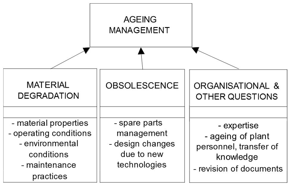
Ageing is a phenomenon that is present in all chemical process industries all over the world. It is sometimes mistakenly believed that ageing is about how old the establishment or the equipment is. Ageing of chemical plants has a wider meaning that goes far beyond corrosion management. Everything associated with a site and its various processes can age, including not only equipment, but also people and procedures. Some ageing phenomena are sometimes only perceived through the lens of a specific activity, such as management of change (e.g., new staff make decisions without full information, e.g., they are not aware of a process’s linkages with another process) or in operational control, where the process itself is outdated relative to modern safety performance standards. In the worst case, an ageing problem may only make itself known through an accident or near miss. For this reason, the effectiveness of the safety management system over time relies on a constant awareness of all the types of ageing impacts – loosely defined as material degradation, obsolescence, and organizational ageing - that affects in equipment, processes and knowledge-based elements.

Figure 3: Categories of ageing (Source: ESReDA Report on Ageing of Components and Systems)
Material degradation
To some extent, there is a tendency to focus on equipment ageing because the signs of material degradation are so tangible. Carbon steel corrosion is the most well-known phenomenon although still, failure to address corrosion failure is a major cause of chemical accidents. In addition to fatigue and vibration, there are also some other forms of degradation that receive far less intention and are even ignored, in particular degradation of nonmetal materials, such as fiberglass and concrete.
Obsolescence
Obsolescence is a phenomenon that may adversely affect equipment, processes and procedures. Equipment reaches the end of its life cycle when the equipment is so degraded by the combination of all the deterioration mechanisms, small changes to operating conditions, and build-up of process fluids over the long term that it can no longer be maintained fit for service. An obsolete procedure is one that no longer can be considered applicable or appropriate because the situation to which it applied has completely changed. Obsolete technology creates risk that replacement parts may not be found or has inherent safety risks that would no longer be acceptable in accordance with current standards.
|
Organisational
The main concern of the ageing organisation is loss of knowledge and expertise. This particular ageing phenomenon is the most challenging to monitor and fix with systematic solutions because it is about trying to compensate for something that is no longer there or not accessible, referring specifically to people and documentation. Indeed, the degradation of performance due to aging of people and procedures can only sometimes be directly observed. On the one hand, procedures and documentation should be associated with each piece of safety critical equipment. Where there are particular imperfections of documentation, especially for older processes and equipment associated with important risk scenarios, the potential impact of lack of information should be assessed and addressed. On the other hand, there are the “unknown unknowns”, such as when there is documentation missing about a change made in years past and no one remembers that it took place. To minimize these kinds of risks, audits and investigations should routinely give attention to ageing dynamics and question to identify where the ageing of various equipment, people and/ processes are emerging as a source of serious risk.
Statistics
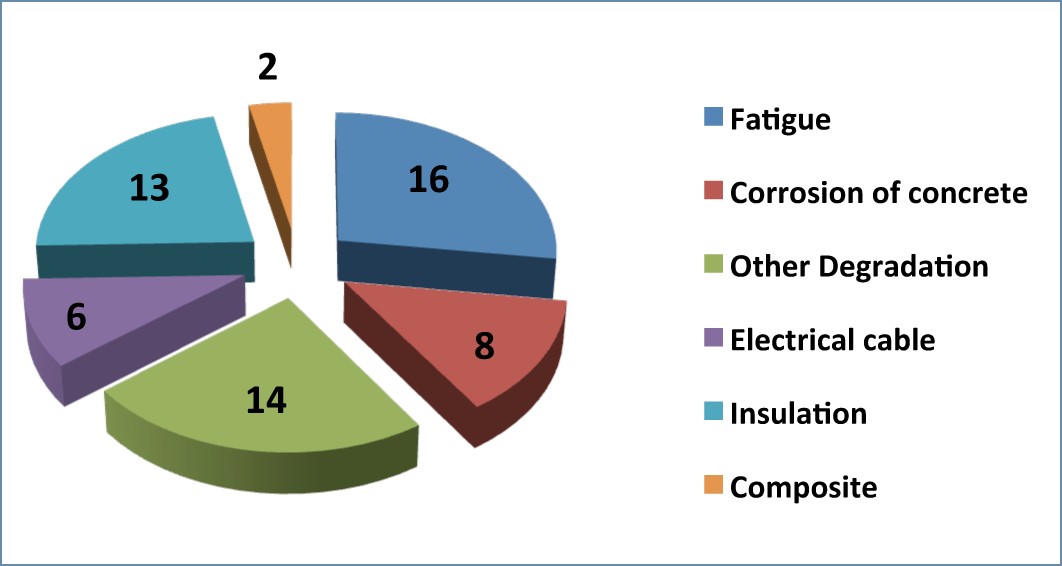
This issue of the Lessons Learned Bulletin offers insight into the importance of approaching ageing as a strategic safety issue with examples of accidents that have learned this lesson only after suffering the consequences. In preparing this bulletin, 69 major accident reports in eMARS were studied together with accidents selected from open sources, such as the Japanese Failure Knowledge Database (http://www.sozogaku.com) and the ARIA database (http://www.aria.developpement-durable.gouv.fr/) operated by the French Ministry of Ecology, Sustainable Development and Energy. Events were chosen to provide a varied perspective on the types of ageing phenomena that can trigger a major accident . The chart below presents the analysis of the selected accidents, based on the type of ageing phenomenon.

Figure 4: Number of major accidents by ageing phenomena (Source: eMARS)
The selected cases also include a number of other lessons learned, not all of which are detailed in this bulletin. The bulletin highlights those that it considers of most interest for this topic, with the limitation that full details of the accident are often not available and the lessons learned are based on what can be deduced from the description provided. The authors thank the country representatives who provided advice to improve the descriptions of the selected cases.
|
Accident 5
Deterioration of composite pipe
Sequence of events
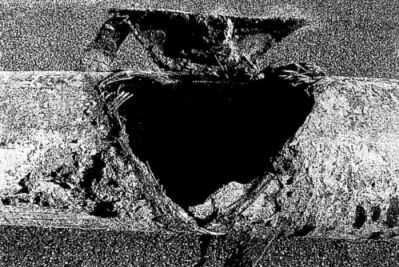
On 7th August 2002, a pipe’s monitoring system detected a 100 m3/h leak with a nominal flow rate 500 m3/h of acid waste water flowing from the manufacturing of dyes and pigments connected to a neutralisation facility located 18 km from a chemical plant. The leak was due to a 40 cm crack on a glass fibre reinforced polymer (GRP) pipeline (NB 400mm). Between 5th and 11th August, a succession of leaks was observed, eight in total. Out of these cases, six leakages occurred on the first two kilometres of the pipeline. The pipe complied with the provisions in the regulations and successfully passed the water resistance test at 15 bar, 20 days prior to the first leak. Following these failures, the pipeline was shut down on 11th August. After the sequence of leakage, a new GRP pipeline was installed which cost more than five million euros which included also the remediation of the polluted soil.

Figure 5: The damaged pipeline (Source: ARIA No. 23562)
Causes
Deterioration of the infrastructure was due to a corrosion mechanism occurring in an acid-stressed environment. A number of factors contributed to this accident. One factor is ageing. The corrosion of the pipe material caused an effective loss of strength. In addition, the process design did not adequately address the pressure surge that could occurwhen the pump is shutdown, in particular, insufficient number of vents made difficult to cope with this situation that is a routine part of the process. Furthermore, there was a failure in installation because of incorrect setting of the surge chamber pressure.
Important findings
• Normally, part of the acid water was conveyed via an NB 300mm pipe to the wastewater treatment facility. The other part of the water was directly released into the Bay of the Seine river, without any specific treatment. However, due to the expansion of the port nearby the chemical site, the plant operator was required to relocate the NB 300mm pipeline, which carried acid water to the wastewater facility, by 31st July 2002. The operator chose to send this water using a GRP NB 400mm pipe that was installed a year before.
|
• Leaks were primarily noticed adjacent to pipe elbows and during directional changes. The pressure never exceeded 5 bar vs. a 10-bar design pressure, in a diluted sulphuric acid medium with a temperature below 35°C. The maximum temperature allowed for GRP tubes was 50°C. Therefore, the fact that failures occurred near or at high points and near a change in direction, confirms the role played by hydraulic transitions.
• It was demonstrated that the damage to the pipe was due to a mechanism of stress corrosion in an acid environment. Stress corrosion is a fissuring mechanism that requires a combination of three factors, such as stress or permanent distortion, the material sensitive to the phenomenon and a corrosive environment.
• There was a design problem in this case, due to the insufficient number of vents available to cope with the pressure surge. This is a phenomenon that generally occurs in long pipelines; key factors are fluid velocity, pipeline and rate of valve closure, or in this case, pump shutdown. It can cause a very high pressure surge which travels along the pipe at the speed of sound in the fluid. The vents are provided to alleviate this surge as was the surge chamber - this to minimize any low pressure surge as the pump is shut down.
• It was also found that certain failures occurred in a zone where it was difficult to correctly compact the soil, nearby pipeline and concrete well.
• The majority of the failures, six out of eight, occurred in the first two kilometers in the zone where hydraulic stresses are greatest.
Lessons learned
• Although the pipes and their assembly complied with the provisions in the regulations as required by the project service order, the installation of the pipe and pressure control systems were not in accordance with good custom and practice. In particular, they were not compliant with the original installation specification, sizing of the buffer chamber and calculation of the number of vents required.
• The operator exchanged the NB 300mm pipeline that conveyed acid water to the wastewater facility with a GRP NB 400mm pipeline. Modifications to the process plant, either in equipment itself or in its connections, in instrumentation, in chemicals, or in process conditions can affect the design integrity and bring about additional risks. Normally, a management of change procedure should be conducted to ensure that changes are properly reviewed and approved prior to implementation.
• The investigation also revealed that the management of the project was the primary cause of several of the faults in design and installation. In particular, the systematic pre-checking of calculations and the installation conditions for the pipe and compliance with various rules for pressurising the facility did not conform with established requirements. When making changes to older processes, the project managers need access to all associated documentation.
• Deficiencies in project management should be addressed in the site’s safety management system as well as the overall site management system, since poorly controlled projects can affect other outcomes besides safety. However, there is also a question as to whether the project contractors had access to the original installation specifications. This can demonstrate that process knowledge has to be maintained and transferred. Accident analysis should highlight these kinds of failure that occur most commonly in older plants.
• Even without the mistakes in design and installation, corrosion of critical components of the equipment would ultimately have led to failure, and therefore, should be subject to a systematic inspection program similar to all safety critical elements.
[EMARS Accident #417 ARIA No. 23562. Similar accident EMARS Accident # 771] |

