Link to .pdf
Link to Seveso Inspection Series Home Page
CIC - Emergency Isolation Systems
DEFINITION AND SCOPE
The purpose of an emergency isolation system (EIS) is to isolate a part of the installation from the place where a loss of containment (LOC) has occurred, thereby preventing the substances in the isolated part to be released. Hence, an EIS is a mitigating measure that is activated after a loss of containment has occurred.
Emergency Isolation System is not a synonym for Emergency Shut Down System (ESD system) which may comprise more elements, such as shutting down energy input or stopping reactions by injecting killing agents. Emergency isolation is however part of most ESD system and sometimes coincides with it completely.
There are other strategies to limit the quantities released after an LOC besides emergency isolation, such as depressurising, transferring the content of a leaking vessel to another vessel, injecting water to displace hydrocarbons at the location the leak. These strategies are outside the scope of this document. However it is important to point out that these operations are not without risks and therefore they should be the subject of a risk analysis. For the personnel operating the plant, adequate instructions and training should be provided.
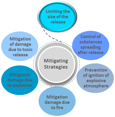
Figure 1. Emergency isolation systems can limit the size of the release and mitigate incident effects.
COMPONENTS OF AN EIS
The functioning of an EIS has three basic components:
- The detection of the LOC
- A decision to take action
- The closure of one or more valves.
Detection of a leak can be achieved in several ways:
- Automatic detection of substances released, i.e., gas detection, hydrocarbon detection, fire detection, etc.
- Visual detection by personnel (directly or via camera)
- Abnormal changes in process parameters (e.g., a sudden fall in level or pressure, increase in flow rate can all be an indication of a LOC).
The decision to take action can be:
- Assigned to an individual (responding to an alarm or based on observation)
- Made automatically, i.e., an automatic detection can be linked to an automatic action.
As for the valve, the following options exist:
- Remotely operated shut off valves (ROSOV)
- Manually operated shut off valves
- Self-operating valves (such as non-return valves (or ‘check valves’) and excess flow valves).
ROSOVs are on/off valves that are powered by a pneumatic or electrical actuator and can be closed from a distance. Manually operated shut off valves need to be closed on the spot using man power.
Self-operating valves combine the 3 functions (detection, decision, action) in one device. These valves are operated by the changes in the flow caused by the pressure drop following a major leak or rupture. Non-return valves will close automatically when the direction of the flow alters. Excess flow valves will close when the flow rate exceeds a certain value. Consequently, an excess flow valve may not operate in case of a relatively small leak, causing insufficient increase in flow rate for the valve to be actuated. These self-operating valves can only be used in pipelines with a unidirectional flow.
SPECIFYING AN EIS
The operator should have determined the EIS based on the need and a clear set of specifications.
Specifying the need
The operator should have identified the need for implementing EIS in its installations. Typically EIS are considered:
- On tanks and vessels containing hazardous substances (storage tanks, reactors)
- On sections of transport piping (such as between storage and production)
- In loading and unloading installations for hazardous substances
- On leak prone type of equipment such as (large) compressors or pumps.
Recommendations can be found in literature. Some companies have their own decision criteria, often based on the type and quantities of the substances present in a vessel.
On storage tanks containing hazardous substances EIS are specifically relevant for the bottom lines, entering or leaving the tank below the liquid level. In case of a leak in these lines there is the potential for the entire tank to be released.
Specifying the type of EIS
Once the need for an EIS has been identified, choices need to be made about the technical implementation, such as
- A self-operating valve, a manual valve or remotely operated valve
- Automatic detection or detection based on human observation
- Automatic action based on (automatic detection) or decision by personnel on site.
On a more detailed level, several safety-related issues need to be considered in the design and operation of remotely operated valves (e.g., fail safe behaviour, fire resistance). In the sections below, several aspects of the design of EIS are discussed in further detail.
SAFETY CONSIDERATIONS
Whatever choices are made by the operator, they should be well documented and motivated.
Automatic detection or detection by operators?
Often there is no continuous presence of operators within a process installation. In such a case it is not realistic to count on human observation for a quick detection of an LOC. A timely detection will in those circumstances require automatic systems.
The use of sudden changes in process parameters as an indicator of a LOC may not always be feasible but it deserves consideration since it is basically a matter of using existing information (e.g., level, pressure, etc.) and requires no additional hardware.
Human detection is an option were continuous presence of operators can be guaranteed, such as in case of loading or unloading activities that are permanently supervised.
Automatic response to LOC detection or decision by operators?
The fastest response can be achieved by an automatic activation of the ROSOV by the detection system. This is of course only possible in case of automatic detection.
However in some cases, operators may want to have a human intervention in order to avoid spurious activation of the ROSOV. Typically, this could be the case for continuous processes where shut downs (and subsequent start-ups) are complex and involve certain risks.
When opting for a human decision, various considerations need to be taken into account.
Alarms (generated by the detection system) should be generated at a location that is permanently occupied by personnel trained to respond to the alarms and activate the EIS. The alarms should be given the necessary priority so they stand out from other alarms. Displaying gas alarms on a lay-out plan of the installation helps significantly to determine the location and the size of a release.
Clear instructions should be given on how to respond to these incoming alarms. It is not unusual for control room personnel to respond to incoming alarms by going outside to assess the situation in the field, before taking action (such as activating the EIS). There are 2 problems involved with this: loss of time and danger for the person going outside.
In case of a (real) LOC (no false alarm) the person going outside exposes himself to a potentially dangerous situation (e.g., explosion, fire, toxic exposure,…). Therefore, in case of multiple alarms (reducing the probability of a spurious alarm), it is advisable to assume a LOC has actually occurred and to activate the EIS immediately and to avoid unnecessary exposure during an intervention outside.
Manually or remotely operated valves?
In general manually operated shut off valves are an inferior solution compared to ROSOV’s. The main disadvantages of a manually operated shut off valve are:
- It requires a person to go into the installation (where a LOC has occurred)
- It takes more time to operate a manual shut off valve, since activation time includes the time for a person to go out and reach the location where the valve is installed.
ROSOV’s are therefore the preferred solution for EIS. In case the operator relies on manually operated shut off valves (for EIS purposes), he should be able to demonstrate that the human factors have been taken into account and more specifically that:
- They can be safely operated (especially in case of an LOC)
- They can be operated in a reasonable time delay after detection of the LOC
- There are always trained personnel on site to operate the manual valves.
Fail position of a ROSOV in case of a power failure
The operator should have specified the behaviour of the ROSOV in case the power source to the valve actuator is interrupted (instrument air for pneumatic actuators and electrical power for electrical actuators).
In general, the ROSOV system should be fail-safe, meaning that a ROSOV should close in case of loss of power. However, in some cases, the operator might select another option: ‘fail-last’ (the valve remains in its last position) or ‘fail-open’. This would typically be the case for continuous production installations where the ROSOV’s are in the open position under normal operating conditions and inadvertent closure of valves might introduce serious upsets and associated risks.
When the fail position of a ROSOV is not ‘close’, the operator should be able to motivate its decision. In addition, measures should be taken to allow closure of the ROSOV even in case of power loss. This can be achieved by:
- For pneumatically operated valves: by providing a local buffer with instrument air allowing at least one more movement of the valve
- For electrically operated valves: by linking the actuator to an electrical emergency of backup power system.
Operability of the ROSOV in case of fire
Closure of a ROSOV should also be guaranteed in case of fire. One option is to have fail close valves and allow electrical wiring for remote control, electrical cables for power supply (in case of electrical actuators) or tubing for instrument air (in case of pneumatic actuators) to melt and be interrupted. To this end, plastic tubing is used for instrument air (instead of metal tubing).
In case of fail-open or fail-last valves, a first option is to have the valve closed by a fire detection system (if any). In order to operate the valves in case of a fire, fire protection should be provided for cabling and tubing for steering and powering the valve.
Another option is to combine the ROSOV with a non-return valve or an excess flow valve (depending on the direction of the normal flow), that can take on the shut-off function in case of a fire.
Fire resistance of valves
In case a ROSOV can be exposed to fire, the valve should have a fire resistance rating that is compatible with the fire scenario (more specific with the expected duration of the fire).
The fire resistance rating allows the valve to remain its integrity (no leaks to the environment) and its tightness (its shut off function) for a certain time.
The fire safety of a valve should be demonstrated by a vendor certificate, proving the valve has successfully passed a fire test, such as the European norm “EN ISO 10497 - Testing of valves requirement of fire resistance”. This standard specifies a maximum allowable leak rate.
The valve should be built into the installation using gaskets with a fire resistance rating. This resistance must be compatible with the fire scenario.
Keeping ROSOV’s in operation
Sometimes automated valves are bypassed with manual valves. If possible, this should be avoided for ROSOV’s, because when the manual bypass valve is open, closing the ROSOV will have no effect (the flow will continue through the open bypass valve). In case however a bypass valve is installed and deemed necessary, it should be locked in the closed position. A procedure should be in place to open the manual bypass valve only in controlled circumstances and for a minimal period of time.
When starting up an installation (e.g. after a shutdown) there should be a documented verification (e.g. via a checklist) to make sure the ROSOV’s are operational.
Risks associated with closure of EIS shut off valves
The operator should have identified any risk introduced by the closure of the shut off valve, such as:
- water hammer
- deadheading pump
- process upsets upstream or downstream of the ROSOV.
Water hammer can be avoided by controlling the closure time of the valve.
Periodic testing
All components of an EIS should be tested periodically:
- The valves (manual as well as remotely operated valves should be operated regularly to make sure they are not stuck and that they are closing tightly)
- Backup power systems (for valves that don’t close in case of power failure)
- The activation buttons (in control room or elsewhere).
Non return and excess flow valves should be tested periodically as well.
All systems used to detect an LOC and triggering an alarm or directly the closure of ROSOV’s should be tested as well.
Tests should be conducted following a test procedure and the results should be documented.
Questions for Seveso Inspectors
This questionnaire relates to Emergency Isolation Systems.
These questions are closed and should be answered positively. Negative answers can only be accepted if a company can demonstrate it has an alternative solution in place or if the question is not relevant or applicable.
A good way to start this inspection to ask the company for their approach regarding emergency isolation and to give an overview of the EIS they have installed. Risk analysis documents can be consulted to verify whether emergency isolation has been addressed.
Specifying the need for EIS
- Has the operator identified the need for implementing EIS in its installations?
- Did the operator evaluate the need for installing EIS on tanks and vessels having a considerable hold-up of hazardous substances?
- Did the operator evaluate the need for installing EIS on sections of transport piping with a considerable hold-up of dangerous substances (such as pipelines between storage and production facilities)?
- Did the operator evaluate the need for installing EIS on loading and unloading installations for hazardous substances?
Detection of loss of containment
- Did the operator provide the necessary measures for detecting (major) LOC’s in a reasonably short time after they occurred (so that emergency isolation will reduce significantly the amount of released substances)?
- Did the operator consider installing automatic detection systems (gas, liquid), especially in area without permanent observation by personnel)?
- Did the operator consider monitoring abnormal deviations in process parameters (level, pressure,...) as a way of detecting a loss of containment?
Response to detection of LOC
- In case a response by an operator is needed: are the LOC detection alarms given in a location that is permanently occupied by an operator that can respond to the alarm?
- In case a timely response by an operator cannot be guaranteed, will the EIS shut off valve be activated automatically upon detection of a LOC?
Fail position of a ROSOV in case of a power failure
- Can the operator guarantee the operation of the ROSOVs in case of a power failure (loss of instrument air of electrical power to valve actuator)?
- For ROSOV’s with a ‘fail last’ or ‘fail open’ position: is backup power provided to allow closure in case of a power failure?
Operability of the ROSOV in case of fire
- Can the operator guarantee the operation (closure) of the EIS in case the EIS shut off valves are exposed to fire?
Keeping ROSOV’s in operation
- Do the EIS valves that can be exposed to fire, have a (certified or otherwise demonstrated) fire resistance rating?
- Have fire proof gaskets been used for the installation of the shut off valves that can be exposed to a fire?
Keeping ROSOV’s in operation
- If ROSOV’s can be bypassed by a manual valve, is there a system in place to keep these manual valves in a closed position and to open them only under controlled conditions?
Risks associated with closure of EIS shut off valves
- Did the operator identify possible risks introduced by the closure of the EIS shut off valves?
- Did the operator evaluate the risks of a pressure surge as a result of the (too fast) closure of ROSOVs?
Periodic testing
- Are all automatic detection systems periodically tested?
- Are all EIS shut-off valves periodically tested?
- For fully automatic EIS: is the entire loop (from detection to action) periodically tested?
- Are any non-return valves or excess flow valve used for emergency isolation periodically tested?
PDF versions for printing
Go back to the Common Inspection Criteria website