Link to .pdf
Link to Seveso Inspection Series Home Page
CIC-Maintenance of Primary Containment Systems
Definition and scope - Background - Primary containment systems and barriers - The role of inspections - Technical measures - Maintenance programme strategy - Competence of maintenance staff - Human factors - Organisational measures
Publication of Common Inspection Criteria is intended to share knowledge about technical and organisational measures and enforcement practices related to major hazard control and implementation of the Seveso III Directive. The criteria were developed by Seveso inspectors to aid the dissemination of good enforcement and risk management practices for the control of major industrial hazards in Europe and elsewhere. This particular topic highlights the issues that are critical for maintenance of primary containment systems. Note that this document is not intended as a technical standard nor as a summary or replacement of any existing standards on the matter.
DEFINITION AND SCOPE
This document provides common inspection criteria to guide inspectors in assessing the adequacy of the arrangements made by operators of Seveso III establishments for maintaining primary containment systems so as to minimise the risk of loss of primary containment of hazardous materials (liquid leaks and gas releases) that could lead to a major accident causing damage to human health, the environment and property. Under the Seveso Directive, these technical and organisational measures should be communicated in the operator’s Major Accident Prevention Policy and implemented through the Safety Management System (SMS). The document provides a reference framework for inspecting how these elements are implemented and can be demonstrated at Seveso establishments. It also can be a means to assess an operator’s performance using defined success criteria.
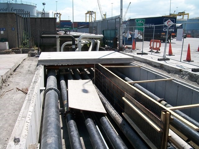
Figure 1. Oil pipelines exposed for maintenance (Photo credit: Eric Jones) [2]
BACKGROUND
Research shows that 50% of European major hazard ‘loss of containment’ events arising from technical plant failures are primarily due to ageing plant mechanisms such as erosion, corrosion, fatigue, as well as other physical stressors on the equipment. One notable study estimated that, between 1980 and 2006, there were 96 potential losses of containment incidents reported in the EU’s Major Accident Reporting System (eMARS, formerly MARS, database) primarily caused by ageing plant mechanisms. This number amounted to 30% of all reported EU major accidents events in the database over the 26 year period, and 50% of the events in the database associated with technical integrity of equipment and control and instrumentation. The study calculated that these ‘ageing’ events equated to an overall loss of 11 lives, 183 injuries and over €170 Million in economic losses. [1]
PRIMARY CONTAINMENT SYSTEMS AND BARRIERS
Figure 2 is an illustration of the bow tie model that is often applied in analysis of scenarios involving the accidental release of hazardous substances. The central point (‘Top Event’) of the bow tie for the typical Seveso hazard is the loss of primarycontainment. Preventive barriers are shown along threat lines, each representing the different possible mechanisms of hazard release that have been identified through the risk assessment process.Note that preventive barriers can be of several types [5], typically :
- Passive (e.g., steel containment envelope) or active, i.e., detection of a threat or error, decision to take action, and execution of that action (e.g., as overfill protection)
- Hardware (e.g., level transmitter, logic solver and automatic valve)
- Human (e.g., operator observing a level indicator, deciding to close a valve and closing the valve) or
- Combined hardware and human (e.g., high-level alarm, operator decision and action to close valve)
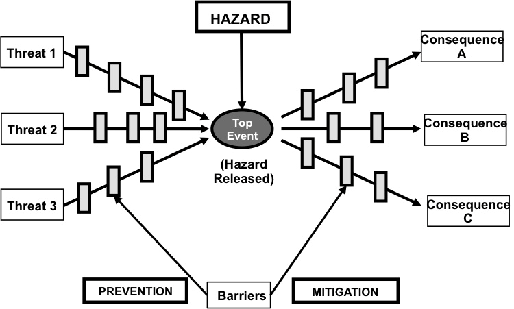
Figure 2. Bow Tie Hazard Barrier Model
This CIC is concerned with the maintenance of the hardware elements of prevention barriers, since they are the hardware elements that are or make up primary containment systems. The primary containment system is the sub-set of safety critical elements (SCEs) that are, or form the hardware components of, preventive barriers. (It is evident from the above description of barriers that these systems will also have human and organisational elements, but it is the maintenance of the hardware elements that is the focus of this CIC.)
The following is a non-exhaustive list of primary containment systems:
- Pressure vessels (including heat exchangers, columns reactors, fired heaters, etc.)
- Atmospheric storage tanks
- Rotating equipment (pumps, compressors, turbines, etc.)
- Valves
- Piping systems (pipe, fittings, flanges, supports, etc.)
- Pipelines inside the Installation (above ground or buried)
- Technology-specific containment systems, g., driers, filters, condensers, cooling towers, refrigeration systems, powder handling systems, underground storage, cryogenic storage vessels, oil and gas wells, wellheads, flowlines, mine tailings disposal ponds, dams, etc.
- Supporting structures for the above
While often not considered as primary containment systems in themselves, it is important not to overlook the following since they contribute significantly to the integrity of primary containment systems[1]:
- Instruments, control systems, alarms and automatic shutdown systems associated with the above, including sensors, process connections, transmitters, tubing and fittings, cabling systems, etc.
- Relief systems (pressure relief valves, vent and flare systems, etc.)
Some particular known weaknesses of primary containment systems are:
- Small bore piping and instrument tubing
- Pump seals
- Bolted joints / flanges
- Corrosion under insulation (CUI) and corrosion under pipe (CUP) supports
- High process temperatures, aggressive chemicals or high cycling rates (temperature or pressure)
- Obsolescence of electrical controls & instrumentation (EC&I) equipment
- Equipment items that are difficult to access
- Newly installed equipment
- Auxiliary items not directly involved in production such as:
- Secondary / back-up pumps
- Emergency shutdown (ESD) systems
- Calibration of alarms and trips
- Temporary and experimental equipment
- Equipment shared between installations, such as internal connecting pipelines
THE ROLE OF INSPECTIONS
The role of inspections is to verify the adequacy of both technical and organisational measures. The following section lists the essential elements of a programme for maintaining primary containment systems on a major hazard site, and the technical and organisational measures that should be in place to support each element. Each measure is accompanied by a list of elements that can be used as evidence that the technical measure is in place. In many cases, typical characteristics of such elements are also provided to help an inspector evaluate whether they are complete and appropriately specified.
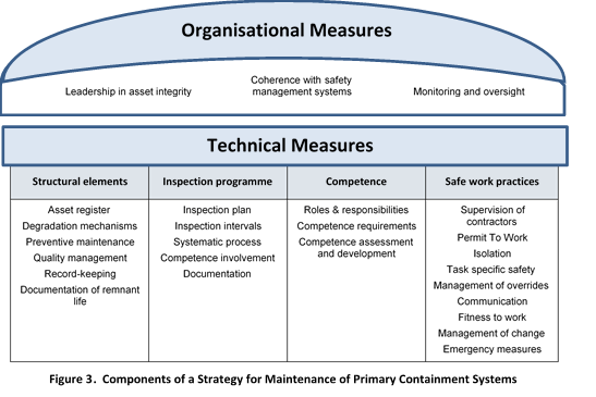
TECHNICAL MEASURES
Technical measures are divided into four categories in this document, as described below:
- The maintenance programme strategy as defined by the structural elements of the maintenance program. The strategy establishes a reasonable balance of preventive and reactive maintenance activities and determines the frequency and scope of maintenance interventions, including the rationale and logic behind the strategy
- Arrangements for identifying, examining and assessing safety critical elements (SCEs)
- Competence requirements of maintenance staff
- Safe systems of work, integrating human factors good practice
The operator is expected to describe these elements in the safety report / major accident prevention policy (MAPP) and have documentation with full details on how they are implemented within the safety management system. [6]
-
Expectation: Maintenance programme strategy, structural elements of the maintenance programme
The maintenance programme should have in place a number of structural elements that form the logical basis for making rules, taking decisions and performing actions involving maintenance interventions. With a well-structured maintenance programme, the operator should be able to identify and track the mechanical integrity of each SCE throughout its life on the basis of demonstrated knowledge about its actual condition and potential degradation pathways. The aim is to ensure that all necessary information is available, and that all systems and processes are primed to ensure that equipment in operation is always fit for service and that degradation does not happen faster than it should.
For this purpose, the operator is expected to establish and maintain the following: [6] [7]
- An asset register, listing and identifying all SCEs by tag numbers and locations of equipment items and line numbers and locations of piping systems and pipelines, and stating their operating limits and minimum performance criteria
- Identification of degradation mechanisms that are credible for each SCE. The operator should be able to demonstrate with documented evidence how they have established their maintenance program, based on the kinds of degradation expected and assumed in the design, and the actual degradation observed in service, with justification of mechanisms not considered credible. Typically corrosion, erosion and fatigue are the most important mechanisms, but the operator should have identified all of the credible degradation mechanisms for each SCE, each of which will be subject to its own specific degradation mechanisms, depending on its design and the conditions of its service and operating environment. Some common degradation mechanisms are:
- Corrosion (internal and external) e.g., chemical, galvanic, microbial
- Erosion
- Fatigue
- Other mechanisms related to specific materials, service or environment, e.g., stress-corrosion, creep, embrittlement, settlement, seismic, physical impact, over-stress, ultra-violet radiation (UV) damage (e.g., to flexible hoses and electrical cables)
- Degradation mechanisms specific to EC&I, e.g., instrument drift, software failures, etc.
- Preventive maintenance plans that establish defined interventions and intervals for each SCE, e.g., cleaning, lubrication, replacement of lifed components (Heat exchanger tubes, glands, gearboxes, batteries, etc.) based on:
- Regulations, codes of practice, industry standards and manufacturers’ instructions
- Degradation data and trend analysis from records of operator’s inspections, reactive maintenance and condition monitoring systems
- Quality management of maintenance work consists of verification procedures to assure that the equipment is safe for performing maintenance prior to beginning the work, in particular:
- Quality control (QC) inspection of work after maintenance has been completed to ensure that equipment is safe and fit for service, before the equipment is returned to service and at critical stages of the maintenance process (e.g., verifying that the pump has been closed after replacement of the impellor or seals, or testing before return to service).
- Quality management of spares and consumable parts[2]. Some particular known weaknesses are:
- Specification and procurement of spares and consumables
- Control of the issuing of spares and consumables for maintenance jobs
- Records of all preventive and reactive maintenance for each SCE, including:
- Date, preventive maintenance (PM) or reactive maintenance (RM) work done and parts replaced
- Reason for the reactive intervention, i.e., the mode of failure, degradation or malfunction
- Historical trend analysis to identify degradation mechanisms and rates, mean time between failures (MTBF), etc.
- Analysis of any PM backlogs and corrective action taken
- Records of other maintenance-related issues, e.g.:
- Operation outside of design envelope (e.g., over/under pressure or temperature)
- Identification of maintenance errors (and corrective actions)
- Identification of unmanaged changes in plant or service conditions (and corrective action)
- Documentation justifying each SCE remaining in service, based on:
- Calculation of remnant life as designed or if life has been extended from the original design, the calculation of the new life expectancy, if the original life has expired
- Assessment of fitness for service by a competent person using a recognised standard
- Expectations: Operator inspection programme - Arrangements for the periodic examination and assessment of SCEs
The operator should have an inspection plan that identifies the various inspection intervals for each type of equipment, on the basis of a transparent logic, that is documented, such that there is an historic record for all the interventions associated with each SCE. For this purpose, the operator is expected to establish and maintain the following:
- A periodic examination and assessment plan based on the asset register and the degradation mechanisms and rates determined above, and based on the principles of Risk Based Inspection. [9]
- Inspection intervals should be established to confirm that minimum performance criteria are met based on the expected rate of degradation and the actual condition when last inspected. The expected rate of degradation should be based on relevant historical data, manufacturing recommendations, or industry standards, adapted as necessary to reflect actual process conditions and updated when there is a meaningful change (e.g., increase in volume, change in substance properties). [8] [9]
- A systematic process and documentation for the routine inspection of an SCE as well as for reverification of its technical integrity after the SCE operating limits have been exceeded beyond predefined values.
- Involvement of the necessary competences in inspections planning as appropriate to the different types of SCEs in service and processes and substances involved.
- Records of all examinations and assessments of each SCE:
- Date, the type of examination performed, and results
- Historical trend analysis to identify degradation mechanisms and rates
- Recommendations to management from the operators’ inspection and technical integrity personnel or, as appropriate, other relevant specialists for specific types of substances or equipment
Expectations: Competence of maintenance staff – including contractor personnel
The operator should demonstrate that appropriate competences are routinely engaged in maintenance planning and execution and maintenance decisions are taken with involvement of relevant expertise. Maintenance tasks should be conducted by personnel with appropriate skills and training such that the work is performed safely and the finished work meets all relevant technical standards and safety requirements.
The operator is expected to establish and maintain the following:
- Defined roles, responsibilities, accountability, authority and interrelation of all people who manage, perform or verify the maintenance and inspection of primary containment systems, based on an analysis of the safety-critical tasks and procedures [10] of:
- The operator’s maintenance programme
- The operator’s inspection programme
Organigrammes, and statements of roles and responsibilities and who supervises whom, should always be justified based on the nature of the safety critical tasks analysis.
- Defined competence requirements of all the above people, based on:
- Individual responsibilities for specific tasks and procedures and specific equipment worked on
- The hazards of the establishment’s processes, including dangerous materials and energies that could exist in the working environment
- Non-technical skills such as vigilance, communication, team work, situation awareness, and decision-making
- Records of competence assessments and skills development of personnel assigned to specific maintenance tasks, including:
- Knowledge and proficiency tests (e.g., type or content of test, date, score received) that demonstrate that the person has the necessary competence and training and that this knowledge is up to date
- Experience in performing the specific task(s), including the last date the individual performed the task(s)
- Gaps in training, experience, knowledge, etc., and actions taken to address gaps (e.g., training, experience, supervision, support)
- Process to verify that the contract company also keeps records of competence assessments and has provided training, supervision and other support delegated in the contract
The Seveso Inspection Series CIC on Training of Personnel is included as a reference at the end of this document. [11]
-
Expectations: Safe systems of work, integrating human factors good practice [12] [13]
The operator should demonstrate that standard safety practices are followed in all aspects of the maintenance work. The operator is expected to establish and maintain the following:
- Safe working practices, procedures and records that:
- Include detailed work instructions in appropriate detail and simple job aids, such as checklists
- Are clear and easily accessible, in a form those involved can understand and use
- Were designed and developed with the active involvement of those who use them
and that cover the following:
- All maintenance tasks
- All periodic examination and assessment (‘operator inspection’) tasks
- Supervision of contractors
- Permit To Work [14] [15]
- Isolation and making the area safe for maintenance and activities
- Management of overrides of process safeguarding systems and process safety alarms
- Communication within and between shifts, including handover
- Fitness to work, including
- Fatigue management
- Supervisor referral to health professional if concerned about an individual’s fitness to work
- Any other human factors good practice applicable to the task
- What to do in an emergency or if a safety risk emerges
- Management of changes to the maintenance task as planned
ORGANISATIONAL MEASURES
Organisational measures include how responsibilities and accountability for achieving the maintenance programme goals are defined and shared. They also encompass the systems and processes within the organisation that support the implementation of the maintenance programme. In this context, the operator is expected to establish and maintain the following:
- Clear overall responsibility for asset integrity of the establishment (e.g., a nominated ‘asset manager’), including:
- Leadership in communication of a vision and supporting objectives and targets for process safety management of the asset
- Encouragement of feedback and learning from process safety incidents and audits
- Obtaining support from other parts of the organisation, including budget, purchasing, and other resource management functions
- Direct access of the operator’s inspection staff and technical authorities to the asset manager
- Segregation of reporting lines and authorities within the operator’s management structure for operations and maintenance functions vs. inspection functions
- Compatibility and coherence with other relevant elements of the safety management system, especially:
- The process and criteria for determining the Safety Critical Elements
- The management of change process for incorporating plant changes and evaluating their safety implications, including changes in operating conditions affecting maintenance management
- Clear criteria for approving
- Restart of a plant after shut down, confirming its technical integrity after maintenance or inspection
- Restart of an SCE that has been subjected to operating in environmental conditions that exceed the design parameter
The use of a ‘Statement of Fitness’ signed by the asset manager before restarting a plant is one good example of such a practice.
- Monitoring and oversight of asset integrity and maintenance operations
- Regular frequent audit of asset integrity by the operator
- Management review of the effectiveness of maintenance management
- Prioritisation and management of corrective actions
- Metrics, for example, statements of fitness, audits, compliance with risk-based inspection intervals, competence assessments and gaps, etc.
REFERENCES
[1] UK Health and Safety Executive. RR823. Managing Ageing Plant - A Summary Guide. http://www.hse.gov.uk/research/rrhtm/rr823.htm
[2] Oil pipelines exposed for maintenance in Alexandria Road. https://www.geograph.ie/photo/3755308 @Copyright Eric Jones and licensed for reuse under this Creative Commons Licence: Attribution-ShareAlike 2.0 Generic (CC BY-SA 2.0). https://creativecommons.org/licenses/by-sa/2.0/
[3] European Commission Joint Research Centre. Common Inspection Criteria for Safety Instrumented Functions. Seveso Inspection Series. JRC82509. https://minerva.jrc.ec.europa.eu/EN/content/minerva/f30d9006-41d0-46d1-bf43-e033d2f5a9cd/publications
[4] European Commission Joint Research Centre. Common Inspection Criteria for Pressure Relief Systems. Seveso Inspection Series. JRC114567. https://minerva.jrc.ec.europa.eu/EN/content/minerva/f30d9006-41d0-46d1-bf43-e033d2f5a9cd/publications
[5] Center for Chemical Process Safety (CCPS) and The Energy Institute. 2018. Bow Ties in Risk Management: A Concept Book for Process Safety. The American Institute of Chemical Engineers, Inc.
[6] UK Health and Safety Executive. Guidance on COMAH Regulations: Regulation 8 – Safety Reports. http://www.hse.gov.uk/pubns/books/l111.htm
[7] UK Health and Safety Executive. COMAH Competent Authority Ageing Plant Operational Delivery Guide. http://www.hse.gov.uk/comah/guidance/ageing-plant-core.pdf
[8] UK Health and Safety Executive. CRR 363/2001 Best practice for risk based inspection as a part of plant integrity management. http://www.hse.gov.uk/research/crr_htm/2001/crr01363.htm
[9] API 581: Risk Based Inspection Methodology - Recommended Practice (Third edition, April 2016)
[10] Energy Institute. Guidance on human factors safety critical task analysis. March 2011. REF/ISBN: 9780852936030. https://publishing.energyinst.org/topics/process-safety/leadership/guidance-on-human-factors-safety-critical-task-analysis
[11] European Commission Joint Research Centre. Common Inspection Criteria on Training of Personnel. Seveso Inspection Series. To be published. https://minerva.jrc.ec.europa.eu/EN/content/minerva/f30d9006-41d0-46d1-bf43-e033d2f5a9cd/publications
[12] Energy Institute. Human and Organisational Factors Guidance. https://publishing.energyinst.org/topics/human-and-organisational-factors
[13] UK Health and Safety Executive. Guidance on Human Factors and Ergonomics. http://www.hse.gov.uk/humanfactors/index.htm
[14] UK Health and Safety Executive. HSEG250 - Guidance on permit-to-work systems. http://www.hse.gov.uk/pubns/priced/hsg250.pdf
[15] European Commission Joint Research Centre. Common Inspection Criteria for the Permit to Work System. Seveso Inspection Series. JRC93841. https://minerva.jrc.ec.europa.eu/EN/content/minerva/f30d9006-41d0-46d1-bf43-e033d2f5a9cd/publications
[1] The Seveso Inspection Series CICs on Safety Instrumented Functions and on Pressure Relief Systems are included as references at the end of this document. [3] [4]
[2] Spares are replacements for parts of the machine, e.g., a pipe, a valve, etc. Consumables are items that are used that are used within the process, e.g., oils and lubricants, coolant, etc.
PDF Version for printing
No. 9 Maintenance of Primary Containment Systems
Go back to the Common Inspection Criteria website