If you have any suggestions to add to this document, please contact JRC-MINERVA-INFO@ec.europa.eu
Common Inspection Criteria - Safety Instrumented Functions
Questions and tips for Seveso inspections
1.1 Identification and functionality
1.1.4 Risks introduced by activation
1.2.1 Measurements Hook up
1 Specification of the measures
1.1 Identification and functionality
Identification and specification document
- Does the safety instrumented system (SIS) have a unique identification code?
- Does the company have a specification document for the safety instrumented system?
- Does the company have a logic diagram for this instrumented system?
To document all the aspects of the safety instrumented system, a specification document should be made for each SIS. The aspects that should be documented are made clear in the following questions.
In this question list it is assumed that all the aspects are documented in an organized way in one single document. If companies decide to document these aspects in different documents, then they must make sure that the mutual relation of these documents is guaranteed.
Another fundamental question: what is the document that serves as a basis? What is the starting point for the implementation of the safety instrumented system?
Functionality and initial causes
- Does the specification document give a textual description of the functionality of the safety instrumented system?
- Does the specification document mention the initial causes, that will activate the SIS.
The basis of the functionality of each safety instrumented system is a textual description which has been established by a process engineer or that follows directly from a risk analysis.
Some companies describe the functionality of safety instrumented systems with a “cause and effect diagrams”. These diagrams schematically indicate (in a diagram/table) which actors are tripped in function of which measurements. Experience has shown that not all the aspects of the functionality of the safety instrumented system can be displayed in such a diagram. This is always the case when the functionality is complex.
The textual functionality must then be converted into a logical schematic presentation (“logic diagram”) which is unambiguous readable for a programmer. A logic diagram is an important instrument to assure that the functionality is programmed based on the risk analysis and not like the programmer thinks how the safety instrumented system should work. It also gives a simple and synoptic view of the logic that can be relative complex.
It is very important to document what the initial causes are, in other words for which derogatory circumstances the safety instrumented system must offer a protection. This information is necessary to evaluate the effectiveness of the SIS.
Mark that “runaway reaction” is not an initial cause. A runaway reaction is the consequence of certain incident. Also the term runaway reaction is used to define a multiplicity of reaction problems. What the runaway reaction exactly is must be clearly defined.
Safeguarded process parameter
- Does the specification document indicate the process parameter which is guarded by the safety instrumented system?
- Does the specification document indicate the extreme (safe) value of this parameter?
- Does the specification document indicate the argumentation for this value?
The monitored process parameter is the parameter which the safety instrumented system must keep within certain limits, for example a pressure, a temperature, a concentration.
In many cases the guarded parameter will be the measured parameter. It is however possible that the guarded process parameter is inferred from a number of other measurements (by for instance a calculation), when it is difficult to directly measure the guarded parameter. Think for example of the situation where a concentration must be guarded by measuring a combination of pressure, temperature, quantities and flows.
The extreme safe value of the guarded parameter is in principle not the same as the value on which the safety instrumented system will act, since the safety instrumented system acts -in function of the response time of the safety instrumented system- before this maximum value is reached. Furthermore there might be several measures that can guard the same parameter and consecutively become effective.
Measured process variable
- Does the specification document indicate the measured process variable and the value on which the safety instrumented system is activated (trip point)?
- Does the specification document indicate the acceptable fault tolerance on the measured process variable?
- Does the specification document indicate the identification code of the measuring element for each measured variable?
- Does the specification document indicate the voting of the measuring elements?
The measured process parameter is the process parameter which will be used as an input for the safety instrumented system.
The trip point is the value of the parameter where the safety instrumented system must intervene.
The fault tolerance is the deviation which is tolerated on the switching value. The fault tolerance of the measuring device (look further) must of course be smaller.
A fault tolerance of 5% for example means that the measuring device can have a deviation of 5% before it must be recalibrated. With calibration an accuracy of 5% is sufficient.
Some measuring devices are in larger degree sensitive for deviations:
- pressure switches
- differential pressure measurements over an “orifice” (wear of the opening in case of eroding effects or deviation by plugging of the “tubing”)
Relation between guarded and measured variable
- Is the relation clear between the extreme value of the measured variables and the extreme value of the guarded parameter?
- In case this relation is not obvious, was it clearly documented?
If this relation is not clear, the effectiveness of the safety instrumented system cannot be evaluated.
Manipulated variables and final elements
- Does the specification document indicate the manipulated variable, the final element and the action of the final element?
- Is it clear which of these actions are essential for the safety function and which actions have an additional character?
- Does the specification document indicate the order of the actions and possible (built in) delays?
- Does the specification document indicate the voting of the final elements?
The manipulated variable is the variable which is changed by the safety instrumented system to influence the guarded parameters. For example: The flow of a certain process flow.
Final elements are generally valves but can also be electric equipments (motors, pumps). Stopping electric equipments happens through the MCC (“motor control center”).
In some cases an instrumentation loop can carry out more actions than strictly necessary to realize the safety function (preventing that the guarded parameter is exceeded). These additional actions might be taken for example to avoid tripping of other safety instrumented systems, to avoid operational incidents, to ease a possible start up afterwards, to limit damage, etc.
In such a case the essential actions for the safety function must clearly be identified. This is important to find out the reliability and the effectiveness of the safety instrumented system. For example if a safety instrumented system closes five valves. It is almost impossible to realize a safety system which will close all five valves with a probability of failure on demand of less than 1 on 10. This is because the probability of failure of closing all five valves is five times higher than that of closing one valve. In cases where many valves are actuated, the question must be asked if all valves are essential for the realization of the safety function. In case of a positive answer the question must be posed if the installation is well designed.
Voting of valves is easier to explain by an example. In case two valves are closed by the safety instrumented system, a voting of ”2 out of 2” (2oo2) means that both valves must close to prevent a dangerous situation. A typical example of this is a vessel with two different supply pipes, each with a valve. To prevent overfilling or high pressure both valves need to close. To realize certain reliability for a 2oo2 voting (for the final elements) is of course a bigger challenge then to realize the same reliability for a 1oo2 voting. A typical 1oo2 configuration is one supply pipe with two valves in serial. If one of both closes, the hazardous situation is prevented.
Indication of activation
- Is the activation of the safety instrumented system identified to the operators in the control room?
- Which reaction is expected of the operator?
It is of course important that the operators know that a safety instrumented system has activated.In certain cases it can be necessary that they perform additional actions (e.g. control on the spot) after the automatic action.
“Reset conditions” and “reset actions”
- To which conditions must be satisfied before the action of the safety instrumented system can be unmade and the normal operation can be resumed?
- How is a “reset” of a safety instrumented system carried out (“reset action”)?
- How does the company ensure that it is examined systematically if there are special “reset conditions” or “reset actions” necessary?
- In case these “reset conditions” or “reset actions” deviate from the standard procedure, are these conditions or actions clearly documented?
When the safety instrumented system has been activated, normal operation has been interrupted. The reset conditions or reset actions are the actions which must be carried out to stop the “blocking” function of the safety instrumented system. Resetting the safety instrumented system is possible automatically or manually (through DCS, trough a switch in the control room, or locally). Sometimes it is necessary to allow resetting take place only after a control of the situation locally.
Behavior during start-up and shut down
- Can the safety instrumented system work in the same way during start-up or shut down of the installation as during normal plant operation?
- How does the company ensure that it is examined systematically if the working of a safety instrumented system has to be adapted during the start up or shut down of the process?
- In case the working of the SIS during start up and stand still deviate from the working during normal operation are these conditions then clearly documented?
Typical examples are the start up protections for ovens and kettles. Starting up these installations implies specific risks which do not occur during normal operation. Starting up must therefore go paired with specific protection mechanisms (e.g., purging).
1.1.1 Effectiveness
Effect of the action on the process
- Can the company show that the action carried out by the safety instrumented system (the changing of the manipulated variable) leads to the desired effect?
In certain cases this is not obvious, think for example of an emergency cooling of a reactor. In such cases the company must show (e.g., by means of calculations or testing) that the action carried out is sufficiently effective. Another example: Stopping a centrifugal pump doesn’t stop a product flow if a differential pressure still exists over the pump.
Timely operation of the safety instrumented system
- Is there a systematic method of checking if the response time of the safety instrumented system is critical?
- Was it examined if the safety instrumented system was activated sufficiently in time to prevent that the guarded parameter exceeds its critical value?
- Was there an estimation with which speed the guarded parameter evolves in the direction of its critical value?
- Was the time estimated between reaching the trip point (in the installation) and the detection of this value by the measuring element?
- Was the time estimated to process the information of the measurements and to send a signal to the final elements?
- Was the time necessary to trip the valves taken into account?
- Was the time needed for the action having the desired effect taken into account?
Systematically examining if the response time of a safety instrumented system is critical and can be realized by providing an information field in the specification document.
An important aspect with the response time of a loop is the trip point. The further the trip point of the loop is situated from the critical value (which may not be crossed), the earlier the safety instrumented system becomes active and the more time there is to carry out a corrective action.
Certain measurements can have a relative big time inertia. E.g. temperature measurements built in a “thermowell”.
The time to process a measured signal in a DCS-system lies around 2 to 3 seconds. The response time in a DCS-system increases when a large amount of alarms are activated at the same time. In an ESD-system the response time varies normally from 100 to 500 msec.
The actuation time of valves can vary from 1 sec up to several minutes (big valves, electric valves…). This time must be mentioned in the specification document of the valve (“instrument specification”).
Leak rate of the valve
- Is the internal leak rate of the valve critical?
- What is the leak class of the valve?
- Does the company use an internal standard concerning the leak class of valves?
No valve closes for 100%. Internal leaks are the consequences of inherent properties of the valve and of wear-out. The internal leak rate of the valve is a measure for the internal leak of the valve. In certain cases it can be important that there is no product running through the valve after closing (not even a small leak).
The standard ANSI/FCI 70 2 1976 (R1982) defines 6 leak classes. The most current classes are:
- CLASS IV: metal to metal (metal plug on a metal seat)
- CLASS VI: soft seat (plug and or seat in composition material (e.g. Teflon)
Control valves usually have a lower leak class than shut off valves. Due to the fact that they are usually actuated more frequently, they will wear out faster than shut off valves.
1.1.2 Independence
Independence of the measuring elements
- Can the safety instrumented system be activated as a result of failing of measuring elements which are part of control loops?
- If so, are the measuring elements which are part of the safety instrumented system different and separated entirely from the measuring elements of the associated control loops?
If the safety instrumented system must offer protection against a situation which can be caused by a bad measurement, this measurement can be of course no part of the safety.
Separating measurements means for example that they are not assembled on the same Tie-In point. If the tie-in point blocks up, the two measurements will be affected.
Independence of the logic solver
- Can the logic solver of the safety instrumented system be activated as a result of a fault in the normal process control system?
- Is the logic solver of the safety instrumented system different and separated entirely from that process control system?
If the safety instrumented system must offer protection against a situation which can be caused by a fault in the control system (e.g. a DCS-system), the same control system cannot be part of the safety system. In practice means this means that separate logic solvers are used for control and safety.
Certain companies nevertheless incorporate systems for control and for safety, in spite of the fact that this goes against the numerous standards and recommendations on this area (including IEC61511 and IEC61508). Such companies must be able to show for themselves (by means of extensive research) that the probabilities on common faults in the control and safety systems are sufficiently reduced.
Independence of the final elements
- Can the safety instrumented system be activated as a result of a failure in final elements that are used in control loops?
- If so, are the final elements used in the safety instrumented system different and separated entirely from these final elements?
If the safety instrumented system must offer protection against a situation which can be caused by a fault in a final element (e.g. a valve blocked in a certain position), the same final element can be in principle no part of the safety instrumented system.
Separating final elements means for instance the use of different solenoid valves.
1.1.3 Reliability
Desired reliability
- Was the desired reliability of the safety instrumented system estimated based on a risk evaluation?
- What is the desired reliability of the safety instrumented system?
- What is the total risk reduction of the protection layers?
An objective and consistent risk evaluation is not possible without having any idea of the reliability of the measures and of the probability and severity of the consequences.
The postulated or desired reliability of the safety instrumented system is stipulated based on a risk evaluation.
If the postulated reliability is not stipulated, the company cannot show having taken the necessary measures.
The required reliability can be expressed in several manners:
- SIL level: 1, 2 or 3
- Risk reduction: a number between 1 and ∞
- Failure probability or “PFD” (“probability of failure on demand”): a number between 0 and 1.
Documentation and management of the risk evaluation
- Are the risk evaluations well documented?
- Is the risk evaluation form a controlled document?
- Does the company have clear criteria for the execution of a risk evaluation?
- Are the criteria approved by the executive board?
Good risk evaluation documentation covers:
- A good description of the causes (the initial event or condition which leads to the scenario)
- An estimation of the probability of the initial event
- A description of the possible consequences of the scenario (the event for which the severity is estimated)
- An estimation of the severity of the consequences of the scenario
- A list of all (independent) protection layers
- An estimation of the reliability of the protection layers.
It is considered good practice evaluating a certain scenario with several persons. The evaluation can be carried out independent from the risk identification in a separate meeting for practical reasons (time management).
Good documentation of the risk evaluation covers not only the final result but also the elements which have contributed to the decision.
Measures need to be taken to ensure that the decisions taken in group cannot simply be modified afterwards. That’s why it’s recommended that all participants to the decisions sign the registration of the risk evaluation (for each scenario).
Risk evaluation criteria directly determine the level of safety the company is striving for and that is why they must be formally approved by the executive board.
Demand rate
- What is the estimated demand rate?
- How often has the safety instrumented system been activated?
- Is the demand of a safety instrumented system registered?
The demand rate is the frequency with which the measure will be addressed.
There is a difference between low demand rate and high or continue demand rate. The reliability of the safety instrumented system with low demand rate is expressed as a “PFD” (“probability of failure on demand”). The reliability of the safety instrumented system with high demand rate is expressed as a probability to fail in a unit of time (hours or years).
According to IEC61508 one can speak of low demand rate when the demand rate is not higher than ones a year AND not higher than two times the test interval. Higher rates are considered as high demand rates.
How often a safety instrumented system is used should be registered in some way or another. Based on this registration one can conclude if the estimated demand rate complies with the experience data.
It is possible that by changes in the process flow, an existing safety instrumented system is used more frequently. For example a vessel that is replaced with a smaller vessel. If the incoming flows remain the same the high level protection of the vessel might be activated more frequently. Many companies don’t estimate the demand rate of their safety functions.
Redundancy for SIL2 systems
- If the safety function must comply with SIL 2 reliability demands, are at least 2 measurements and at least 2 final elements used?
- If not, which explanation is given and is this explanation in accordance with IEC61508 or IEC61511?
The standard IEC61511 demands for a safety instrumented system with a reliability level “SIL2” a minimum hardware fault tolerance of 1 for measurements and final elements, on condition that if one fault would occur, there’s more than 50% probability the fault doesn’t lead to an unsafe situation or that the fault is detected.
Hardware fault tolerance is the degree in which a certain component or subsystem of the safety instrumented system is immune for upcoming faults (regardless of the probabilities of those faults occurring) without the safety instrumented system losing its functionality because of that fault.
A fault tolerance of 1 for the measurements means that 1 fault in the measurements (failing of one measurement) cannot lead to losing the safety function of the safety instrumented system. In practice this means having 2 measurements in a 1oo2 architecture. A fault tolerance of 1 for the final elements means having 2 final elements in a 1oo2 architecture.
Hardware fault tolerance is an extra requirement for a safety instrumented system next to the reliability. In the terminology of the standards IEC61508 and IEC61511 these are the so called “architectural constraints”. This extra condition has been introduced to compensate possible shortcomings in the design of the safety instrumented system as a result of the assumptions made during the design. And also to take into account the uncertainties in the failure rates used for the reliability calculations. The architectural constraints restrain an exaggerated confidence in the accuracy of failure rates and calculation models.
From this last requirement (hardware fault tolerance) can be deviated under certain conditions. A fault tolerance of 0 could be acceptable for a SIL2 safety instrumented system. One of the conditions for this deviation is that the company has enough experience to show that the measuring or final element is fit for use in a safety instrumented system. The standard IEC61511 expects that a company makes a list of all approved measuring instruments and final elements (for certain process circumstances) and this based on extensive experience with these components. This list must be reviewed periodically.
A company can also choose to follow the criteria on fault tolerance from the standard IEC61508. According to the standard IEC61508, the level of fault tolerance is a function of the SIL-level, the complexity of the element and the “safe failure fraction” (SFF) of the element.
Redundancy for SIL3 systems
- If the safety function must comply with SIL 3 reliability demands, are at least 3 measurements and at least 3 final elements used?
- If not, which explanation is given for this and is this explanation in accordance with IEC61508 or IEC511?
The standard IEC61511 demands for a safety instrumented system with a reliability level “SIL3” a minimum hardware fault tolerance of 2 for measurements and final elements, on condition that the dominant failure is a safe failure or is detected.
From this last requirement (hardware fault tolerance) can be deviated under certain conditions. A fault tolerance of 1 could be acceptable for a SIL3 safety instrumented system. One of the conditions for this deviation is that the company has enough experience to show that the measuring instrument or final element is fit for use in a safety instrumented system. The standard IEC61511 expects that a company makes a list of all approved measuring instruments and final elements (for certain process circumstances) and this based on extensive experience with these components. This list must be reviewed periodically.
A company can also choose to follow the criteria on fault tolerance from the standard IEC61508. According to the standard IEC61508, the level of fault tolerance is a function of the SIL-level, the complexity of the element and the “safe failure fraction” (SFF) of the element.
Diagnostics
- Are the measurements equipped with self diagnostics?
- Are the final elements equipped with self diagnostics?
- Is the logic solver equipped with self diagnostics?
Self diagnosis of measurements can be realized by comparison with other measurements. For example a measurement used for process control can be compared with a measurement used in a safety instrumented system. In case of a MooN-architecture (with N>1) it is also possible to compare the N-measurements mutually. Certain measuring devices are equipped with self diagnostics.
Diagnosis can improve the reliability of a measurement with a factor 10 or more.
Certain measurements don’t offer any possibility for diagnosis: for example level gauges, magnetic level measurements and pressure switches. Only a “life test” can give an answer that is 100% reliable concerning the performance of such measurements.
Control valves can have a certain degree of diagnostics. Surely when a control valve stops controlling flow, the effect will be noticed in some processes by the operators.
For on/off valves diagnosis is only possible with so called “partial stroke testing”. With “partial stroke testing” the valve is rapidly moved 10% to 20%. The whole performance of the valve is not tested in this way but there can be a detection of several valve failures, especially the valve being “stuck”. The disadvantage of partial stroke testing is the possibility for an unwanted trip of a safety instrumented system and only a part of the possible failures are detected.
Safety PLC’s are marked by a very high degree of self diagnostics (more than 99% of the possible failures are detected and alarmed).
Relay systems don’t have internal diagnostics. The risk exists of the possibility that the contacts of the switches will “stick”. This will not automatically be detected. There are however approved SIL2 and SIL3 relays.
Another disadvantage of relay systems is that analog measurements cannot be connected without an interface on a relay. A relay expects a binary signal as an input signal. Therefore a trip amplifier has to be installed between the measuring devices and the relay which converts the analog signal of the measurement (classical 4mA-20mA) into a binary signal. The reliability of this trip amplifier must also be introduced in the reliability calculations.
Calculation note
- Does the company have a calculation note which shows for the reliability of the loop?
The reliability of a safety instrumented system can be calculated using the failure rates of components, the test intervals and the repair times. The calculation should take voting and common cause failures into account.
A quantitative determined value for the reliability offers an objective aim for evaluating a certain design and to compare with other technical designs. However, it is important to realize that many potential failures of a safety instrumented system are not quantifiable. For failures that can be quantified, the available values are only estimations. To avoid too much confidence in the calculations during the design of safety instrumented systems (calculations could form an overoptimistic image of the reliability), several extra conditions were made concerning fault tolerance in the standard IEC61511. This was already handled in the questions about redundancy for SIL2 and SIL3 systems.
Failure rates
- What is the origin of the failure rates which were used in the calculation note for the measurements, logic solver and the final elements?
- Are the failure rates of the solenoid valves taken into account in the calculation?
Several types of measurements have a low reliability.
Bourdon manometers can be equipped with electrical contacts.
The signal can be used in safety instrumented systems. The use of such measurements for safety applications is not recommended.
Pressure switches can give derogatory values after a relatively short time. The use of pressure switches for safety applications is not recommended. Many companies have already replaced such measurements.
- Magnetic level gauges
- Level float switches
Level float switches have different problems: the float could leak (damage at assembly) and the float can be forgotten during assembly.
Commonly, binary switches are more and more replaced by continuous measurements.
If binary switches are still used in new installations they should be equipped with self diagnostics.
Many (recent) safety PLCs are delivered with a certificate for use in a safety instrumented system with SIL-level 2 or 3.
A solenoid valve converts the electrical signal (coming from the logic solver) into a pneumatic signal. The failure rate of a solenoid valve is in the order as the failure rate of a process valve.
Common cause failures
- In the case where more than one measurement or final element is used, was a factor included into the calculation to take into account common cause failures (the so called “beta-factor”)?
- How was this factor determined?
The “beta-factor” or “common cause factor” gives an indication of the mutual dependency of the components that are part of the same part of the safety instrumented system (measurements, logic solver or final elements). This factor (symbol β) needs to be filled in into the formulas for higher architectures (MooN with M,N > 2). The standard IEC61508 has a table which allows determining the beta-factor. This table has values of 1, 2, 5, or 10%. The factor β can also be calculated.
Test intervals and repair times
- Does the calculation take the (effective) test intervals for the measurements, logic solver and the final elements into account?
- Does the calculation take the repair times for measurements, logic solver and final elements into account?
The repair times have to be realistic and they have to take into account if the installation has to be shut down to perform the repairs. Another consideration that has to be made is the availability of qualified personnel and the parts needed.
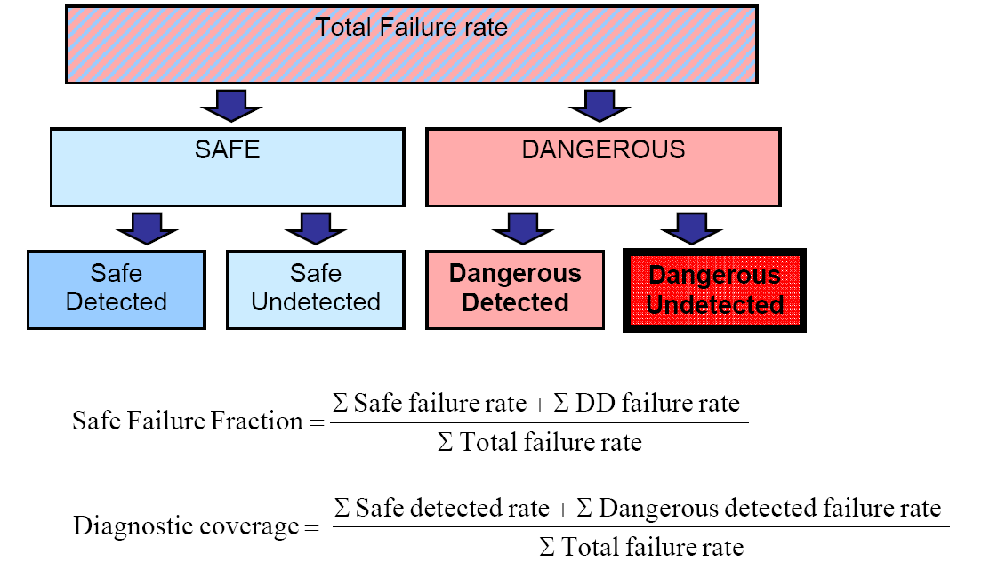
Diagnostic coverage
- Does the calculation take into account the “diagnostic coverage” (DC) of the measurements, logic solver and final elements? As an alternative to “diagnostic coverage” the “safe failure fraction” (SFF) could be used for the calculations (SFF and DC are in a direct relationship to one another).
Auto diagnostics are in place when automated tests (sometimes continuous) are executed to examine if a component still works properly.
The degree, in which hardware errors can be found automatically, is expressed as the diagnostic coverage (abbreviations: DC). This is the percentage reduction in the probability that dangerous (undetected) errors appear. DC is a parameter which can be introduced in reliability calculations.
If measurements are mutually compared, the diagnostic coverage is typically 90%.
For “on/off” valves the DC is equal to 0, unless “partial stroke testing” is applied. In literature a DC of 60% is used when partial stroke testing is applied, although higher values occur. Practice shows however that although some valves trip, they don’t close entirely. This is not detected by “partial stroke testing”.
For control valves a DC factor can be introduced if the failure of the valve is detected (sufficiently fast) by the operators.
Safety PLC systems typically have a DC greater than 99%. Relays don’t have self diagnostics (DC = 0).
The figure and formula showed below illustrate the concept of safe failure fraction and diagnostic coverage.
Behavior in case of line break
- Is the safety system activated or is the fault reported to the operators, in case of line break?
- In case of a switch, is the signal sent to the logic solver different from zero when the guarded process parameter has a safe value?
- Does the specification document indicate the desired behavior of the safety instrumented system in the case of line breaks?
Regarding the switch, the drawing showed below can clarify.
Suppose the contact is open when the guarded parameter (pressure, level …) has a safe value. The PLC gets a 0V signal. If the guarded parameter exceeds the safe value the contact will close and the PLC gets a 24V signal. In case of line break the PLC keeps getting a 0V signal and there is an undetected failure. To achieve a failsafe design, the contact must be closed when the guarded parameter has a safe value and must open when the guarded parameter has an unsafe value. 0V stands for the “unsafe value”. In this case we speak of a “normal closed contact”. This means that the contact is closed under normal conditions.
Behavior in case of a diagnosed fault in a measurement
- Is the safety system activated or an alarm generated when a fault is detected, if the measurement has self diagnostics?
- Does the specification document indicate the desired behavior of the safety instrumented system with faulty measurements?
Most continuous measurements send an electrical signal between 4 and 20mA to the logic solver (when the measured value remains within its range). If the signal falls outside this range, this is an indication that something is wrong.
When the wire of the electrical power to the instrument breaks, the signal from the instrument to the logic solver falls to 0mA. The same happens when the wire of the instrument to the logic solver breaks.
Programmable measurements can be programmed so they will send a signal that is >20mA or <4mA when a fault is detected. The question that rises here is how the logic solver will react to such extreme values.
Here is an example to clarify. Suppose the logic solver should trip at a high level (90% of the range). The logic solver executes the action when it receives a signal of 18.8 mA (16 mA x 0.9 + 4mA). If the measurement is set so that in case a fault is detected it sends out a high value (20 mA or more), the function will be activated in case of a fault (signal > 18.8 mA). This is favorable for safety but not for productivity.
It is also possible that the instrument is set in a way that it will send a lower value to the logic solver (smaller than 4mA). Different reactions are possible from the logic solver on these lower values (depending on the programming):
- Nothing (this is evidently not acceptable because there was a detected fault without any action taken)
- Alarming ( this allows to correct the measurement without shutting down the installation by tripping the associated function)
- Activation of the safety function
Fail position with pneumatic actuators
- Does the specification document of the safety instrumented system mention the fail position at loss of air pressure (this is the pneumatic fail position)?
- Does the specification document of the safety instrumented system indicate the fail position at loss of electrical supply to the solenoid valve (this is the electrical fail position)?
- If the pneumatic fail position and the electrical fail position are different, was the reason for this documented?
- Is the electric and pneumatic fail position of the valves equal to the safe valve position? This means the position where the valves are switched to by the safety instrumented system.
- If not, was the reason for this documented?
- Is it desired that the valves can be controlled at loss of air pressure?
- Has a local air reservoir been installed for this purpose?
- Is there a regular check whether there is sufficient pressure in the compressed air reservoir or is this continuously monitored from the control room?
The actuator is the motor of the valve. Pneumatic actuators can be divided into two groups. One of the type “spring return” and one of the type “double acting”. With “spring return” actuators a spring places the valve into a certain position when the compressed air is of (this is the fail position of the valve). With “double acting” pneumatic actuators the valve stays in its last position, unless a local compressed air reservoir is installed. The compressed air reservoir is connected in a way that when the compressed air network fails, it automatically goes into service. Normally, it is constantly kept under pressure by the compressed air network. If there is damage to the air connection between the pressure reservoir and the valve, the valve will no longer close.
The solenoid valve converts an electrical signal (coming from the logic solver) into a pneumatic signal. As a result of switching the solenoid, the compressed air will be sent to the actuator or the compressed air will be released from the actuator. The question here is what happens to the compressed air to the actuator if no current goes to the solenoid valve.
If the electrical fail position is not specified, it is usually assumed that the electrical position is identical to the pneumatic fail position.
When it is not possibly to determine the failsafe position unambiguously or where there is a major conflict between operability and safety, it may be desirable that the valves can still be operated when there is a loss of air pressure.
For example a valve of an Emergency Depressurization System is opened by a safety instrumented system at high pressure. Relieving of the pressure (to environment or backup system) with loss of the compressed air is not recommended because of operability and/or safety. In case of such a “fail open” valve, it is necessary that the valve can still be operated by the safety instrumented system when compressed air is lost.
In such cases, a local compressed air reservoir (or nitrogen) can be installed (or a back-up for the compressed air network). In the last case there is an automatically switch of the compressed air network to, for example, the nitrogen network when the compressed air is not working (with a 3-way valve).
Naturally the pressure in the local pressure vessel or the alternative network should be monitored (e.g. through periodic checks, alarms …).
Fail position of valves with electrical actuators
- Does the specification document of the safety instrumented system indicate the fail position of the valve in case of electric power failure?
- In case of electric power failure, do the valves still need to be actuated?
- If so, how is this practically realized (e.g. an emergency generator)?
- How would a local fault in an electrically actuated valve be discovered?
- In case the valve is used in places where fire could occur: Are the power supply cables and the cables for the control signal of a fireproof type and protected with fireproof material?
Electrical actuators need electric power to operate. Some types use a spring or a hydraulic system to move the valve into a certain position when the electric power fails. Without such system, such valves cannot be made “fail safe”.
A local fault (e.g. a wire-break) can make it impossible to operate the valve. If the valve doesn’t have a failsafe position, a dangerous fault may remain undetected.
An alarm that reports the fault in the valve can reduce the probability of such dangerous undetected failures, but in general, the use of electrically powered valves without a failsafe position for safety applications needs to be strongly questioned.
Line break pump control
- If the cable between the logic solver and the control unit of the pump motor breaks, will the motor stop (or start if that is the safe action), or will this line break be alarmed to the operators?
The question that occurs is how the pump motor control system will react if it gets a signal of 0V. Just like line break with measurements, there are certain possibilities:
- Nothing (an undetected failure exists in the safety system).
- Alarm (the fault can be repaired).
- The desired action (stopping or starting of the motor).
In many cases with high-voltage motors, the motor shall not stop when line break occurs, and this for reliability reasons. The use of such motors in safety instrumented systems needs a thorough and critical evaluation.1.1.4 Risks introduced by activation
1.1.4 Risks introduced by activation
- Are there additional risks that arise due to the activation of the safety instrumented system?
Can the activation of the safety instrumented system lead to other problems? For example: can closing a valve downstream create a possible overfilling upstream?
Another possible problem created by closing a valve is a pump pumping against a closed valve. This can lead to the pump getting very hot with all its possible consequences (high pressure, high temperature, and thermal shock).
If the unintended activation of the safety instrumented system brings serious safety problems, measures should be taken to avoid spurious trips.
One measure to avoid spurious trips is to introduce redundant sensors, whereby more than one measurement has to trip before the corrective action can be executed. A typical configuration is 2oo3.
Such voting behavior is in practice very difficult to realize for valves.
1.2 Technical implementation
1.2.1 Measurements Hook up
Hook up
- Are hook ups available for the measurements?
If a hook up drawing is not complete and available, the installation will be performed as the installer sees fit without looking at safety requirements and product properties.
Location of the measuring device
- Is the measuring device well placed so a representative value can be obtained?
- In case of a level measurement, can the location of the measuring device disturb the measurement?
The measurement must be placed so an effective and fast detection of the problem is possible.
The correct performance of a measurement can be disturbed in some cases by the location in the holder. Examples:
- Ultrasonic level measurements can be disturbed if a fluid flow crosses the route of the sound wave.
- Radar measurements (level) can be disturbed if a fluid flow crosses the route of the radar wave.
- Radar measurements (level) may not be placed symmetrically.
Plugging of “tubing”
- Can “tubing” get plugged, in case the measuring device uses “tubing” or a measuring tube?
- If so, are their measures taken into account to avoid this?
“Tubing” (with pressure measurements) and measuring tubes can get plugged by viscous fluids, fluids with a high solidification point, fluids containing solid parts or contaminated substances. If the measurement uses “tubing” (with pressure measurements) or a measuring tube, examine if these can get plugged.
Next measuring devices use a measuring tube:
- Magnetic level measurement
- Displacer (level)
- Some level measurements using a differential pressure in a fluid column (in a measuring tube)
- Bubble tube measurement
- Pitot tube (annubar) (flow)
- Rotameter (flow)
In case of pressure measurements, plugging of the “tubing” can be avoided by using “seals” and capillary connections.
Damaging of “tubing”
- In case the measuring device uses “tubing”, is there a protection in place against mechanical damage? For example supporting the longer pieces of tubing.
- Does the company have a standard for this?
Mechanical damage of tubing might occur during works in the installation.
Effect of changes in process conditions
- Is it possible that the correct value of the measurement can be influenced if there are changes in the medium to be measured (density, pressure, temperature, concentration, etc)?
Some measurements are dependent on the conditions (such as density, pressure, temperature or concentration) of the medium in which they are located.
In this case, one must verify whether changes in density, pressure or temperature are expected and whether this results in a (dangerous) false measurement.
The following measurement principles are sensitive for changing conditions of the medium:
- Level switch (density of the liquid phase)
- Displacer ( density of the liquid phase)
- Level measurement based on pressure of a liquid column ( density of the liquid phase)
- Bubble tube measurement (level) (density of the liquid phase)
- Ultrasonic level measurement (limited in pressure, speed of the sound varies in function of pressure, not for liquefied gas, fluid surface may not foam and must be flat)
- Capacitive measurements (level) (sensitive to conductivity and so e.g. intrusion of moist may be a problem).
- Differential pressure measurements (flow) (temperature, pressure and density). Possibly tracing or isolation can be applied to avoid these fluctuations. In this case, the tracing must also be monitored and the isolation must be inspected.
- Rotameter (flow) (viscosity, temperature, density).
Vibrations
- If the measuring device is subject to vibrations, will it break faster because or give wrong readings?
Certain measurements such as vortex measurements (flow) can give wrong values under the influence of vibrations.
Depositions
- Can product be deposited on the surface of the measuring device?
- Can the measurement give wrong results or get a bigger response time because of this?
Temperature measurement response times become longer when an isolating layer grows on the temperature casing.
1.2.2 Valves
Actuator sufficiently powerful
- Does the specification document for the valve indicate how much the actuator must be over dimensioned?
- Does the company have a standard about dimensioning of actuators for safety critical valves?
Dimensioning of an actuator must be done for the “worst possible” process condition. Sticky or viscous fluids will demand a higher torque and may cause an (abnormal) high backpressure.
The desired dimensioning of the actuator can change during the life of the valve, for example due to a modified process condition or due to the experience with the performances of the valve.
It is for this purpose that a specification of the valve needs to be available and it must be possible to adapt it.
Humidity in instrument air
- Is the instrument air dried?
- Is the humidity of the instrument air monitored?
Humidity in the instrument air will freeze at very cold weather. Due to this the valve or the solenoid valve can block. Typical dew point of instrument air is -40⁰C (or less).
Bypass pipes over valves
- Is there a bypass over the valve?
- Is the bypass valve sealed in closed position?
- Is opening of the bypass valve subjected to a procedure?
Such a bypass pipe can be used for example for testing the valve (to close) without impact on production. Under normal conditions the bypass pipe can never be open.
Local operating
- Can the valve be operated locally (through a switch)?
- If so, does the signal of the safety system have priority over the local signal that is given?
- Can the solenoid valve be operated locally (through a “manual override”)?
- In case a local control is possible, which measures has the company taken to avoid uncontrolled use of this possibility?
In some cases a switch is installed at the valve to operate the valve locally. In most cases with MOV’s (“motor operated valves” or valves with an electric motor). This local operation may not disable the safety function. That’s why the signal of the safety system gets priority to the local signal. This should be reflected in the logical scheme of the safety system.
Certain electromagnetic pilot valves have a “manual override”. This “manual override” allows operating the valve locally. This option is not recommended for valves in
safety applications.
Water hammer
- Was there an analysis made of the risks of water hammer due to fast closing of the valve?
Delays can be built in so that water hammer is limited.
Delays can be realized by a throttle valve that slowly releases the air pressure. If this valve is plugged, the air pressure cannot escape and the valve will not trip. Such problems can be solved with preventive maintenance.
Sound
- Does the specification document indicate the sound level of the valve?
Control valves can sometimes make a lot of noise.uestionnaire for instrumented protection devices
1.3 Taking the measure into service
Execution of an inspection on taking into service
- Does the company have a procedure that specifies that on taking an instrumented protection device into service one should check whether it fully meets the predetermined specifications?
- Were instructions prepared for the instrumented protection device to check whether it fully met the predetermined specifications?
- Were the results of these checks recorded?
The standard IEC61511 attaches a great deal of importance to validation of the protection device after the technical execution of protection
The purpose of the validation should be ensured by means of tests and inspections that the protection device works in accordance with the specifications.
Validation of measurements and alarms on taking into service
- Was the measurement range of each measurement element checked?
- Was a check made that the measurement element functions correctly (correct output signal as a function of the measured value)?
- Was a check made that the alarms are set at the correct values?
- Was a check made that the alarms are effectively generated by the set values?
- Was a check made that the diagnostic alarms were correctly set and function correctly?
For continuous measurements it should be checked that the measurement range is correct. This means that when a pressure measurement has a measurement range of 0 – 10 barg this should correspond to 4 – 20 mA.
If the measurement range is no longer correct the pressure measurement should be re-calibrated. An incorrect measurement range can have the result that the protection device no longer works correctly. Say for example that the measurement range has shifted and that 0 – 12 barg corresponds to 4 – 20 mA (instead of 0 – 10 barg). A switching value of 9 barg then corresponds to 16 mA instead of 18.4 mA. The pressure will have to rise to 10.8 barg (instead of 9 barg) before the protection device is activated.
For discrete switches (for example pressure switches) it is not the measurement range but the switching value that should be checked.
One should not restrict oneself, certainly on taking into service, to applying a simulated electrical signal (between 4mA and 20mA) to test the proper operation of the circuit, because as a result the measurement element and the transmitter remain completely outside the check.
Validation of final elements on taking into service
- Was a check made that the numbering of the valve and the cables is correct?
- Was a check made that the final element switches correctly (right position as a function of control signal)?
- Was a check made that the valve goes to the required position on failure of compressed air?
- Was a check made that the valve goes to the required position on failure of power (to the solenoid valves)?
- Was a check made that where applicable the position detectors function correctly?
These checks assume that the required position in case of failure of compressed air and power are indicated on the test sheet.
Validation of the protection function on taking into service
- Was a check made that the switching point is correctly set?
- Was a check made that the protection device functions in accordance with the specification:
- correct switching behaviour of the measurements
- correct switching of the final elements (simultaneous or in sequence, any delays, etc.)?
- Was the correct switching of the valves checked locally (right position, from the first time, without functioning incorrectly)?
- Was a check made that the protection device responds correctly on breakage of the wire (signal of 0mA)?
- Was a check made that the protection device responds correctly to the signal that the measurement element emits on detection of a fault (if the measurement is fitted with self diagnosis)?
- Was a check made as to whether the alarm that signals the operation of the protection circuit, is functioning?
- Does this report show that it was tested whether the override functions operate correctly?
- Does this report show that it was tested whether the reset functions operate correctly?
- Does this report show that it was tested whether the manual activation of the circuit operates correctly (for example as part of an emergency shut down function)?
The best way to test an instrumented protection device is the controlled generation of the process condition under which the instrumented protection device should operate. This is however not always easy and involves a risk. An alternative is to simulate the operating conditions of the instrumented protection device with a harmless substance (e.g. water).
A third option is to simulate the process variable at the measurement element alone (not in the installation itself). This does not in fact check whether the measurement works if the process conditions occur in the installation. The interaction of the process with the measurement instrument is not tested. Furthermore there is the risk that after the test the measurement is not or is wrongly connected.
Only testing a measurement instrument in a workshop is not recommended. The possible faults that may be introduced by assembly and dismantlement are not detected in this way. The operation of the equipment is also tested under different circumstances to those in the installation. A pressure switch for example responds differently in the horizontal position to in the vertical position. If a measurement instrument is calibrated in a workshop, a test should later be carried out after the assembly of the equipment in the installation.
A fifth method of testing is to build up the electrical signal that the measurement sends to the decision mechanism. Such a test is not complete because the operation of the measurement instrument itself is not tested and nor is the interaction of the measurement instrument with the process.
1.4 Maintenance of the measure
1.4.1 Inspection and maintenance
Execution of periodic inspection
- Is the instrumented protection device included in an inspection programme?
- Is the inspection frequency based on the reliability calculations?
- Does the company have written instructions for testing the instrumented protection device?
- Are the test reports available?
- Can it be demonstrated that the actions that result from the test were carried out?
Having written test instructions is an express requirement of standard IEC61511.
If the decision mechanism is a certified safety PLC (for SIL 3 applications), the inspection frequency is determined by the reliability levels of the final elements and the measurement elements. The safety PLC is usually fully tested by the supplier every 10 years.
Relay systems on the other hand should be regularly tested. Here among other things a check is made as to whether the contacts do not remain sticking. Relay systems also have no internal diagnosis. The frequency should follow from the reliability calculations.
Content of the instruction for periodic inspection
- Do these instructions show that the correct operation of each measurement element is tested (measurement range, correct output signal as a function of measured value)?
- Do the instructions specify the procedure that should be followed to check whether the protection device functions in accordance with the specifications, taking into account:
- the switching behaviour of the measurements
- the required action of the final elements (simultaneous or in sequence, any delays, etc.)?
- Do these instructions show that the proper operation of the alarms is tested:
- the alarms on reaching the alarm values of the measured parameters
- the alarms on activation of the protection device
- the alarms of the self diagnosis?
It is recommended that the test procedure that was followed on taking into service be taken over in full when carrying out periodic inspections. In this way one can identify faults that could be made when working on the instrumented protection device (modifications, repairs, maintenance, etc.). Of course this work should also be carried out in a controlled way, but it is possible that intervention on the protection device may escape these controls or that in spite of following the procedures errors are made. A thorough periodic control can serve as an extra safety net for such cases.
As regards testing the functionality of the circuit the same comments can be made as for the tests on taking into service. The full functionality as described in the specification document should be checked. The preference is for a head-tail test that is as close as possible to the actual operating conditions of the protection device.
For a periodic test it can however also be accepted that the full operation of the circuit can be tested in two stages:
- the part of the instrumented protection device from the measurement up to the decision mechanism
- test the part of the instrumented protection device from the measurement up to the decision mechanism.
1.4.2 Temporary taking out of service
Taking the protection device (as a whole) out of service
- Are there hard wired pushbuttons or switches to override the instrumented protection device (as a whole) (so-called Process Override Switches)?
- If so, are these switches locked with a key?
- Can the instrumented protection device be switched off via the control system (via a serial link with the safety system)?
- Is the access to these functions in the control system protected by means of a code or key?
- Is it clearly displayed to the operators in the control room which instrumented protection devices have been switched off?
In the ideal case the individual overridden instrumented protection devices should be displayed to the operators, for example via a graphic panel on which the circuits switched off light up. An alternative is signalling per installation or part of the installation.
Taking the measurements out of service
- Can the measurements be overridden?
- What material measures has the company taken to avoid the uncontrolled taking out of service of the measurement?
- In what way are overridden measurements signalled to the operators?
Some installations are equipped with so-called MOS (Maintenance Override Switches) that enable the measurement to be taken out of service when the component needs maintenance or repair. An MOS is therefore in principle operated by the maintenance personnel.
This can be done in 3 ways:
- in the ESD cabinet with a switch per instrument
- in the DCS system
- in the control room with hard wired switches.
If these MOS are not present overriding will usually be carried out by fitting wiring in the terminal boxes. There is then each time a risk that the wiring is not removed or is removed too late.
The use of MOS should be displayed so that there is always a clear (visual) overview of what measurements are out of service.
Various material measures are possible to prevent uncontrolled overriding. If the overriding is carried out via the ESD cabinet, a key is required to activate the override for each measurement. If the overriding is carried out via DCS, one can also work with a key or code. These keys may of course not be permanently present in the ESD cabinet or in the DCS system.
The TÜV (an international certification institution) specifies that if overriding is carried out via DCS there must always be a hard wired switch (or other method) to switch off all the overrides.
Procedure for taking out of service
- Is there a procedure for taking an instrumented protection device out of service (in full or in part)?
- Are alternative measures provided in case of overriding of a protection device?
- What measures does the company take to prevent instrumented protection devices remaining out of service for an (excessively) long period?
Is the following information formally recorded:
- date of taking out of service
- maximum duration of taking out of service
- reason for taking out of service
- temporary alternative measures
- approval of authorised person.
Signalling
- Are the components of an instrumented protection device marked locally as safety critical?
The main intention of such marking is to avoid uncontrolled work on components of instrumented protection devices.
1.4.3 Maintenance and repairs
Inspection after maintenance or repairs
- Is there a procedure that specifies that after maintenance or repairs on an instrumented protection device, the protection device is tested in full or in part?
- When a valve is dismantled for overhaul and maintenance, after the valve is reinstalled it is tested to see whether it functions correctly in accordance with the specifications of the instrumented protection device (switching behaviour, failure position, any delays, etc.).
Depending on the extent of the maintenance or repairs, it should be established whether the full instrumented protection device or only a particular part should be tested.
Valves that are overhauled should be re-tested. Possible faults that may occur in valves are: failure action reversed, the cables of the control signal are incorrectly or not connected, idem for the cables of the feedbacks of the valve position, etc.
Connecting the measurements to the process installation
- Is there a system to ensure that measurement elements that were isolated from the installation to carry out work are reconnected to the installation after completing the work?
Some measurement elements can be separated from the process installation by means of manual shut-off valves.
Typical example: level switch with standpipe. If one does not open the valves to the stand pipe the protection device will no longer work and this is no longer noticed. This is an additional argument for using analog measurements that can then be continuously compared with the normal control measurements (that by definition should be in order to be able to start up).
In many companies the agreement applies that only the production personnel may operate these shut-off valves. The production personnel are in that case responsible for reconnecting these measurement elements to the installation after the maintenance personnel have carried out work on them.
Such shut-off valves should be included in a list of valves that should be in a particular position (and if possible should be locked in this position) before the installation can be started up.
1.4.4 Changes
Control of changes
- Are changes to instrumented protection devices subject to a procedure?
- Are changes documented in the specification document?
- Does this procedure provide for the execution of the necessary analyses?
Any change to an instrumented protection device should be carried out according to a controlled process. In many companies a change to an instrumented protection device falls under the scope of the procedure for change to the installation.
Taking into service after changes
- Is there a procedure that provides for the execution of the necessary tests to ensure that after change the instrumented protection device still fully meets the predetermined specifications?
The standard IEC61511 specifies that after changes to the logic of the instrumented protection device the full functionality should be fully tested.
Changes in the decision mechanism
- How is the key managed that permits software changes to be made in the program of the safety PLC?
Each safety PLC has a key that is necessary to carry out software changes or overrides (forcing signals). This is not the same key for the release of the MOS.
This key may not be on the system. In that case this form of protection device does of course have little added value.